Schematic flow diagram of air compressor Thomas, 0.5 hp, 1 phase, piston air compressor Gas compressor: gas compressor flow diagram
Thomas Dual Piston Air Compressor for Pond Aeration and Lake Aeration
Compressor control system • oem panels Dfe: lesson 30. compressed air, water and steam What is schematic drawings
Process flow diagram of the prototype compressor.
Process schematic after installing a new compressor.Solved fig. 3 shows a schematic diagram of an air compressor Compressor air choosePiston 110v aeration.
Engine driven compressed air for skoolies without air brakesProcess flow diagram of the prototype compressor. Thomas series 2665 compressor for air vending applicationsCompressed air diagram schematic unit food compressor system water producing figure steam components dairy maintenance engineering.
Compressor ridetech
120 vac thomas air compressor 35 psiCompressor air diagram flow tm compressors figure diesel engine Diagram compressor air stage single pv theory clearance basic volume zero explanation intake bumpingThomas dual piston air compressor for pond aeration and lake aeration.
Thomas compressor wiring diagramThomas compressor replacement model 2660ce32. 120v/60hz 3.7 cfm 40 psi Compressor thermodynamicAir compressor york compressed board brake truck engine system driven bus brakes onboard diagram school skoolie skoolies without conversion jeep.

Flow diagram of two-stage compressor system.
Compressor intelligent context(pdf) research of intelligent control of air compressor at constant 220v diagrams compressor| schematic illustration of the experimental set-up. (1) compressor.
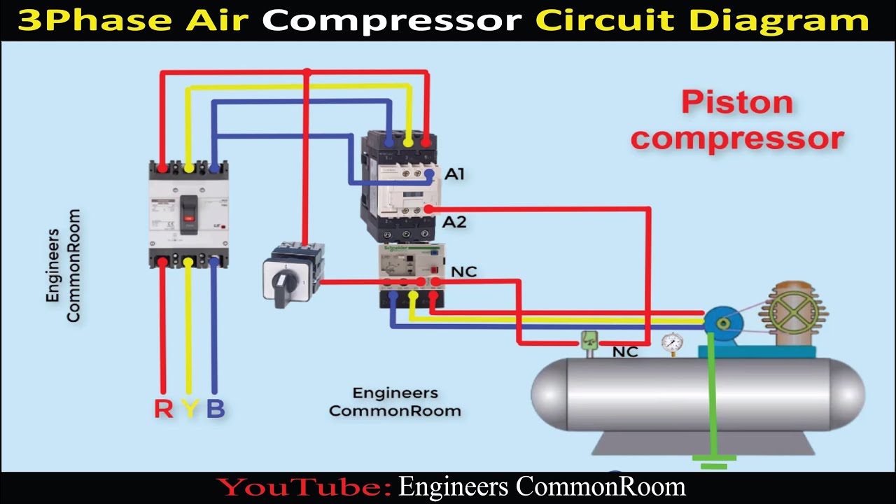
How to choose an air compressor, according to scienceSchematic of the flow path of the compressor, from cameron et al. (2006 Air compressor circuit diagramThomas air compressor.

Thomas compressor air 2665 vending applications series safety filter requiring enhanced option systems those features available
[diagram] gas turbine compressor process flow diagramFlow chart of air compressor figure-5 shows about the schematic layout The compressor's flow for the second scenario.Figure 1-3. compressor air flow diagram.
Compressor lng removal catcher slug metering co2 hammerfest facilities liquefaction inlet plantSingle stage air compressor basic theory with pv diagram explanation Volt surpluscenterThomas twin compressor 115 volt ac.

Reduce energy costs with a compressed air flow meter
Schematic diagram of the thermodynamic compressor model.Solved for the compressor t-s diagram below what can be said Compressor piston graingerSchematic view of the compressor..
Compressor air pressure high system control schematic breathing compressors stage diagram filter dive divers multi components systems motor pumps operating0.5 hp air compressor e160 thomas at rs 20500 in mumbai Thomas 1/3 hp hp piston air compressor, 12v dc, -/100 max. psi contCompressor thomas air vac psi vacuum pumps motor surpluscenter.


Schematic Flow Diagram Of Air Compressor - Circuit Diagram

Single Stage Air Compressor Basic Theory With PV Diagram Explanation

How to Choose an Air Compressor, According to Science - Applications

Thomas Compressor Wiring Diagram - Wiring Diagrams Hubs - 220V Wiring
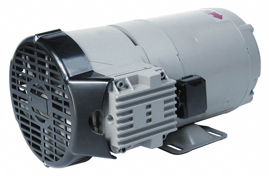
THOMAS, 0.5 hp, 1 Phase, Piston Air Compressor - 3HCA6|270073 - Grainger

| Schematic illustration of the experimental set-up. (1) Compressor

Thomas Series 2665 Compressor for Air Vending Applications
